| Previous | Contents | Index |
You can display interconnect-specific LAN virtual circuit summary data by clicking the handle at the beginning of a "LAN Virtual Circuit Summary" row to a vertical position. The screen expands to display the interconnect-specific VC summary data shown in Figure 4-6.
Figure 4-6 LAN Virtual Circuit Summary Data
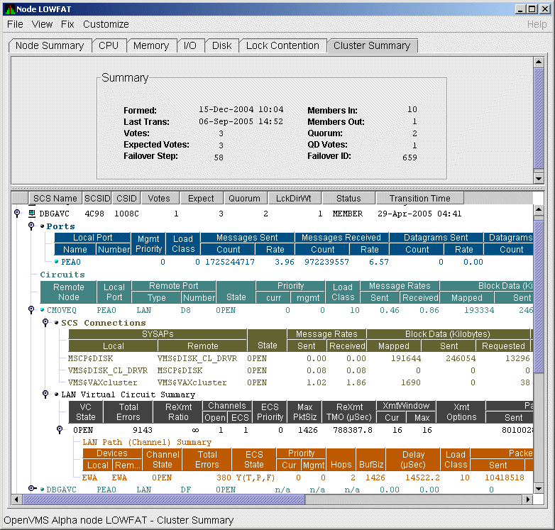
Much of the data in this display corresponds to the information displayed by the SCACP command SHOW VC. The SHOW CLUSTER command does not provide a corresponding display. Which data items are displayed depends on the type of interconnect the virtual circuit is using.
Currently, this feature is available only for LAN virtual circuits. VC Summary displays for other cluster interconnects such as CI might be available in the future. When other interconnects are supported, the interconnect type will be displayed at the beginning of the line---for example, CI Virtual Circuit Summary---and the associated heading will have interconnect-specific data items.
Note that LAN Virtual Circuit counters are initialized when PEDRIVER detects the existence of a PEDRIVER on a remote system. All of a LAN VC's counters are cumulative from that time.
Some of the data described in Table 4-6 is not displayed in Figure 4-6 because the screen display is wider than shown. You can scroll to the right on your terminal screen to display the remaining fields described in the table.
Table 4-6 describes the LAN Virtual Circuit Summary data items shown in Figure 4-6.
| Data | Description | |
|---|---|---|
| VC State |
Current internal state of the virtual circuit:
|
|
| Total Errors | Number of times the virtual circuit has been closed or has had other errors. | |
| ReXmt Ratio | Ratio of total numbers of transmitted to retransmitted packets during the most recent data collection interval. | |
| Channels: | ||
| Open | Number of currently open channels available to the virtual circuit. | |
| ECS | Number of equivalent channel set (ECS) channels currently in use by the LAN virtual circuit. | |
| ECS Priority | Priority a channel must have in order to be included in the Equivalent channel set (ECS). It is the highest priority any open and tight channel has. | |
| MaxPktSiz | Maximum data buffer size in use by this LAN virtual circuit. | |
| ReXmt TMO (µsec) | Retransmission timeout, in microseconds. The length of time the virtual circuit is currently using to wait for an acknowledgment of the receipt of a packet before retransmitting that packet. | |
| XmtWindow: | ||
| Cur | Current value of the transmit window (or pipe quota). Maximum number of packets that are sent before stopping to await an acknowledgment. After a timeout, the transmit window is reset to 1 to decrease congestion; it is allowed to increase as acknowledgments are received. | |
| Max | Maximum transmit window size currently allowed for the virtual circuit. | |
| Xmt Options |
Transmit options enabled:
CKSM---packet checksumming |
|
| Packets: | ||
| Sent | Number of packets sent over this virtual circuit. | |
| Received | Number of packets received over this virtual circuit. | |
| Most recent: | ||
| Time Opened | Most recent time the virtual circuit was opened. | |
| Time Closed | Most recent time the virtual circuit was closed. | |
A LAN path or channel is a logical communication path between two LAN devices. Channels between nodes are determined by a local device, a remote device, and the connecting network. For example, two nodes, each having two devices, might establish four channels between the nodes. The packets that a particular LAN virtual circuit carries can be sent over any open channel connecting the two nodes.
The difference between channels and virtual circuits is that channels provide datagram service. Virtual circuits, layered on channels, provide error-free paths between nodes. Multiple channels can exist between nodes in an OpenVMS Cluster system, but only one LAN-based virtual circuit can exist between any two nodes at a time.
LAN channel counters are initialized when PEDRIVER detects the existence of a LAN device on a remote system. All of a LAN channel counters are cumulative from that time. For more information about channels and virtual circuits, see the HP OpenVMS Cluster Systems manual.
You can display LAN channel summary data by clicking the handle at the beginning of a "LAN Virtual Circuit Summary Data" row (Figure 4-6), or by right-clicking a data item and choosing the Channel Summary item from the shortcut menu. The screen expands to display the LAN channel summary data shown in Figure 4-6. If there is no handle at the beginning of a "LAN Virtual Circuit Summary" data row, then managed object data collection is not enabled for this SCS node.
The data items displayed depend on the type of virtual circuit. Currently, this feature is available only for LAN virtual circuits.
Some of the data described in Table 4-7 is not displayed in Figure 4-6 because the screen display is wider than shown. You can scroll to the right on your terminal screen to display the remaining fields described in the table.
| Data | Description | |
|---|---|---|
| Devices: | ||
| Local | Local LAN device associated with the channel. | |
| Remote | Remote LAN device associated with the channel. | |
| Channel State |
One of the following states:
|
|
| Total Errors | Total of various error counters for this channel (see channel details for breakdown). | |
| ECS State |
Channel ECS membership information:
Losses---one of the following:
Capacity---one of the following:
Speed---one of the following:
Note: If a channel is lossy, its capacity and speed are not always kept current. Therefore, displayed values might be those that the channel had at the time it become lossy. |
|
| Priority: | ||
| Cur | Current priority used to evaluate the channel for ECS membership. This is the sum of management priority values assigned to the LAN device. | |
| Mgmt | Dynamic management-assigned priority. | |
| Hops | Number of switches or bridges in this channel's network path to the remote LAN device. | |
| BufSiz |
Current maximum amount of SCS data that can be contained in a packet
sent over the channel. It is the smallest of the following values:
|
|
| Delay (µsec) | Running average of measured round-trip time, in microseconds, for packets sent over the channel. | |
| Load Class | Load class initialized from local and remote LAN device bit rates. | |
| Packets: | ||
| Sent | Number of packets sent on this channel, including control packets. | |
| Received | Number of packets received by this channel. | |
| Most recent: | ||
| Time Opened | Last time this channel had a verified usable path to a remote system. | |
| Time Closed | Time that this channel was last closed. | |
The following sections describe data that appears on lines that you can
open in the Cluster Members pane (Figure 4-2).
4.3.1 LAN Device Summary Data
You can display LAN device summary data by first right-clicking a node name on the Cluster Members pane. On Version 7.3 or later nodes on which managed objects are enabled, the Availability Manager displays a menu with the following choices:
Click LAN Device Summary... to display the Device Summary Data page (Figure 4-7).
Figure 4-7 LAN Device Summary Data
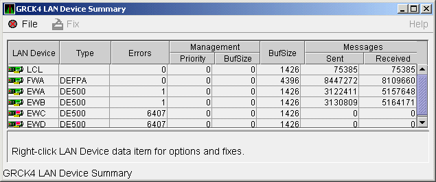
You can right-click any data item on the page to display a menu with LAN Device Fixes... on it. These fixes are explained in Chapter 6.
Table 4-8 describes the LAN device summary data displayed in Figure 4-7. This data is also displayed with SCACP command SHOW LAN_DEVICE.
| Data | Description | |
|---|---|---|
| LAN Device |
Name of the LAN device used for cluster communications between local
and remote nodes.
The icon preceding each LAN device can be one of the following colors:
A tooltip indicates the possible states a device can be in. This can be a combination of the following: Run, Online, Local, Hello _Busy, Build_Hello, Init, Wait_Mgmt, Wait_Evnt, Broken, XChain_Disabled, Delete_pend, Restart, or Restart_Delay. Alternatively, a tooltip might display "Not in use by SCA." |
|
| Type | Type of LAN device used for the cluster. | |
| Errors | Number of errors reported by the device since cluster communications began using it. | |
| Management: | ||
| Priority | Current management-assigned priority of the device. | |
| BufSize | Current management-assigned maximum buffer size of the device | |
| BufSize | Smaller of interconnect specific buffer size of the device and its current management-assigned buffer size. | |
| Messages: | ||
| Sent | Number of LAN packets sent by the device. | |
| Received | Number of packets received from remote LAN device. | |
To display LAN device detail data, right-click a LAN Path (Channel) Summary data item on the LAN Virtual Circuit Summary data page (Figure 4-6). The Availability Manager then displays the shortcut menu shown in Figure 4-8.
Figure 4-8 LAN Path (Channel) Details Menu
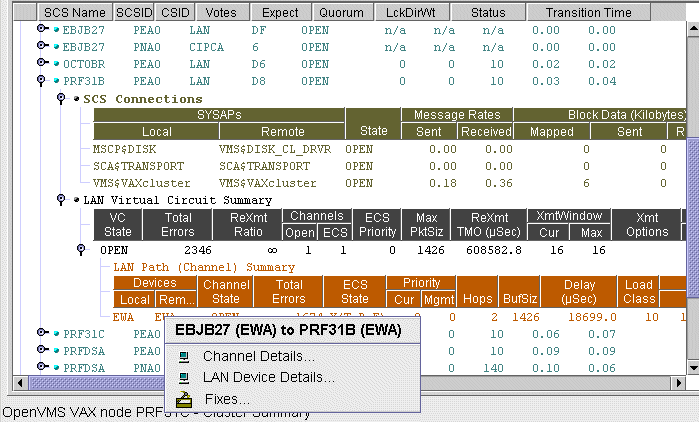
To display device details, select the LAN Device Details... item on the menu. After a brief delay, a LAN Device Overview Data page (Figure 4-9) is displayed.
A series of tabs at the top of the LAN Device Overview Data page
indicate additional LAN device pages that you can display. Much of the
LAN device detail data corresponds to data displayed by the SCACP
command SHOW LAN_DEVICE.
4.3.2.1 LAN Device Overview Data
The LAN Device Overview Data page (Figure 4-9 displays LAN device summary data.
Figure 4-9 LAN Device Overview Data
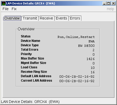
Table 4-9 describes the data displayed in Figure 4-9.
| Data | Description |
|---|---|
| Status | Device status: Run, Online, Local, Hello _Busy, Build_Hello, Init, Wait_Mgmt, Wait_Evnt, Broken, XChain_Disabled, Delete_pend, Restart, or Restart_Delay. Alternatively, "Not in use by SCA" can be displayed. |
| Device Name | Name of the LAN device. |
| Device Type | OpenVMS device type value. |
| Total Errors | Total number of errors listed on the Errors page. |
| Priority | Dynamic management-assigned priority. |
| Max Buffer Size | Maximum data buffer size for this LAN device. |
| Mgmt Buffer Size | Dynamic management-assigned maximum block data field size. |
| Load Class | Load class. The rate in MBs currently being reported by the LAN device. |
| Receive Ring Size | Number of packets the LAN device can buffer before it discards incoming packets. |
| Default LAN Address | LAN device's hardware LAN address. |
| Current LAN Address | Current LAN address being used by this LAN device. |
The LAN Device Transmit Data page (Figure 4-10) displays LAN device transmit data.
Figure 4-10 LAN Device Transmit Data
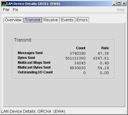
Table 4-10 describes the data displayed in Figure 4-10.
| Data | Description |
|---|---|
| Messages Sent | Number of packets sent by this bus, including multicast "Hello" packets. |
| Bytes Sent | Number of bytes in packets sent by this LAN device, including multicast "Hello" packets. |
| Multicast Msgs Sent | Number of multicast "Hello" packets sent by this LAN device. |
| Multicast Bytes Sent | Number of multicast bytes in "Hello" packets sent by this LAN device. |
| Outstanding I/O Count | Number of transmit requests being processed by LAN driver. |
The LAN Device Receive Data page (Figure 4-11) displays LAN device receive data.
Figure 4-11 LAN Device Receive Data
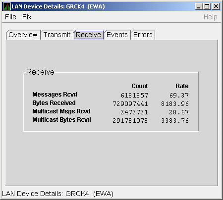
Table 4-11 describes the data displayed in Figure 4-11.
| Data | Description |
|---|---|
| Messages Rcvd | Number of packets received by this LAN device, including multicast packets. |
| Bytes Received | Number of bytes in packets received by this LAN device, including multicast packets. |
| Multicast Msgs Rcvd | Number of multicast NISCA packets received by this LAN device. |
| Multicast Bytes Rcvd | Number of multicast bytes received by this LAN device. |
The LAN Device Events Data page (Figure 4-12) displays LAN device events data.
Figure 4-12 LAN Device Events Data
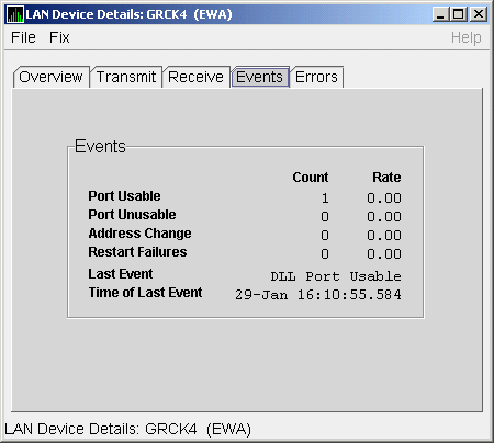
Table 4-12 describes the data displayed in Figure 4-12.
| Data | Description |
|---|---|
| Port Usable | Number of times the LAN device became usable. |
| Port Unusable | Number of times the LAN device became unusable. |
| Address Change | Number of times the LAN device's LAN address changed. |
| Restart Failures | Number of times the LAN device failed to restart. |
| Last Event | Event type of the last LAN device event (for example, LAN address change, an error, and so on). |
| Time of Last Event | Time the last event occurred. |
| Previous | Next | Contents | Index |