![[Compaq]](../images/hp.gif)
![[Go to the documentation home page]](../images/buttons/hp_bn_site_home.gif)
![[How to order documentation]](../images/buttons/hp_bn_order_docs.gif)
![[Help on this site]](../images/buttons/hp_bn_site_help.gif)
![[How to contact us]](../images/buttons/hp_bn_comments.gif)
![[OpenVMS documentation]](../images/hp_ovmsdoc_sec_head.gif)
| Document revision date: 15 July 2002 | |
![[Compaq]](../images/hp.gif) |
![[Go to the documentation home page]](../images/buttons/hp_bn_site_home.gif)
![[How to order documentation]](../images/buttons/hp_bn_order_docs.gif)
![[Help on this site]](../images/buttons/hp_bn_site_help.gif)
![[How to contact us]](../images/buttons/hp_bn_comments.gif)
|
![[OpenVMS documentation]](../images/hp_ovmsdoc_sec_head.gif)
|
|
| Previous | Contents | Index |
Use the SDA command SHOW LAN/COUNT to display information about the LAN adapters as maintained by the LAN device driver (the command shows counters for all protocols, not just PEDRIVER [SCA] related counters). Example F-4 shows a sample display from the SHOW LAN/COUNT command.
| Example F-4 SDA Command SHOW LAN/COUNTERS Display | |||||||
|---|---|---|---|---|---|---|---|
$ ANALYZE/SYSTEM
SDA> SHOW LAN/COUNTERS

LAN Data Structures
-------------------
             -- EXA Counters Information 22-JAN-1994 11:21:19 --

Seconds since zeroed         3953329    Station failures                   0
Octets received          13962888501    Octets sent              11978817384
PDUs received              121899287    PDUs sent                   76872280
Mcast octets received     7494809802    Mcast octets sent          183142023
Mcast PDUs received         58046934    Mcast PDUs sent              1658028
Unrec indiv dest PDUs              0    PDUs sent, deferred          4608431
Unrec mcast dest PDUs              0    PDUs sent, one coll          3099649
Data overruns                      2    PDUs sent, mul coll          2439257
Unavail station buffs(1)            0    Excessive collisions(2)          5059
Unavail user buffers               0    Carrier check failure              0
Frame check errors               483    Short circuit failure              0
Alignment errors               10215    Open circuit failure               0
Frames too long                  142    Transmits too long                 0
Rcv data length error              0    Late collisions                14931
802E PDUs received             28546    Coll detect chk fail               0
802 PDUs received                  0    Send data length err               0
Eth PDUs received          122691742    Frame size errors                  0

LAN Data Structures
-------------------
        -- EXA Internal Counters Information 22-JAN-1994 11:22:28 --

Internal counters address   80C58257    Internal counters size            24
Number of ports                    0    Global page transmits              0
No work transmits            3303771    SVAPTE/BOFF transmits              0
Bad PTE transmits                  0    Buffer_Adr transmits               0

Fatal error count                  0    RDL errors                         0
Transmit timeouts                  0    Last fatal error                None
Restart failures                   0    Prev fatal error                None
Power failures                     0    Last error CSR              00000000
Hardware errors                    0    Fatal error code                None
Control timeouts                   0    Prev fatal error                None

Loopback sent                      0    Loopback failures                  0
System ID sent                     0    System ID failures                 0
ReqCounters sent                   0    ReqCounters failures               0

      -- EXA1 60-07 (SCA) Counters Information 22-JAN-1994 11:22:31 --

Last receive(3)       22-JAN 11:22:31    Last transmit(3)    22-JAN 11:22:31
Octets received           7616615830    Octets sent               2828248622
PDUs received               67375315    PDUs sent                   20331888
Mcast octets received              0    Mcast octets sent                  0
Mcast PDUs received                0    Mcast PDUs sent                    0
Unavail user buffer                0    Last start attempt              None
Last start done       7-DEC 17:12:29    Last start failed               None
   .
   .
   .
|
The SHOW LAN/COUNTERS display usually includes device counter information about several LAN adapters. However, for purposes of example, only one device is shown in Example F-4.
| Field | Description |
|---|---|
| (1) Unavail station buffs (unavailable station buffers) | Records the number of times that fixed station buffers in the LAN driver were unavailable for incoming packets. The node receiving a message can lose packets when the node does not have enough LAN station buffers. (LAN buffers are used by a number of consumers other than PEDRIVER, such as DECnet, TCP/IP, and LAT.) Packet loss because of insufficient LAN station buffers is a symptom of either LAN adapter congestion or the system's inability to reuse the existing buffers fast enough. |
| (2) Excessive collisions |
Indicates the number of unsuccessful attempts to transmit messages on
the adapter. This problem is often caused by:
If a significant number of transmissions with multiple collisions have occurred, then OpenVMS Cluster performance is degraded. You might be able to improve performance either by removing some nodes from the LAN segment or by adding another LAN segment to the cluster. The overall goal is to reduce traffic on the existing LAN segment, thereby making more bandwidth available to the OpenVMS Cluster system. |
| (3) Last receive and Last transmit |
The difference in the times shown in the Last receive and Last transmit
message fields should not be large. Minimally, the timestamps in these
fields should reflect that HELLO datagram messages are being sent
across channels every 3 seconds. Large time differences might indicate:
|
F.4 Troubleshooting NISCA Communications
F.4.1 Areas of Trouble
Sections F.5 and F.6 describe two likely areas of
trouble for LAN networks: channel formation and retransmission. The
discussions of these two problems often include references to the use
of a LAN analyzer tool to isolate information in the NISCA protocol.
Reference: As you read about how to diagnose NISCA
problems, you may also find it helpful to refer to Section F.7, which
describes the NISCA protocol packet, and Section F.8, which describes
how to choose and use a LAN network failure analyzer.
F.5 Channel Formation
Channel-formation problems occur when two nodes cannot communicate
properly between LAN adapters.
F.5.1 How Channels Are Formed
Table F-6 provides a step-by-step description of channel formation.
| Step | Action | ||||||
|---|---|---|---|---|---|---|---|
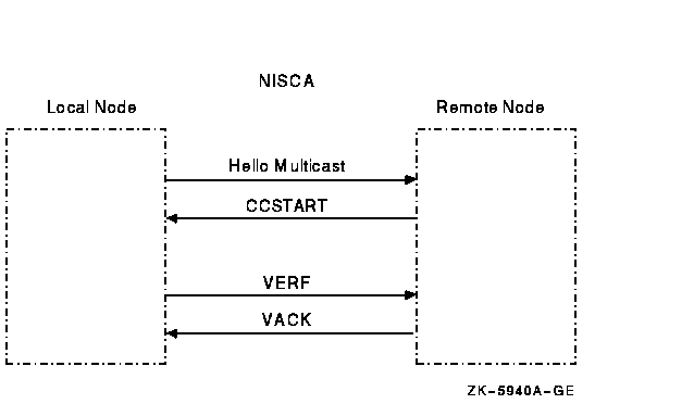
| 1 | Channels are formed when a node sends a HELLO datagram from its LAN adapter to a LAN adapter on another cluster node. If this is a new remote LAN adapter address, or if the corresponding channel is closed, the remote node receiving the HELLO datagram sends a CCSTART datagram to the originating node after a delay of up to 2 seconds. | ||||||
| 2 | Upon receiving a CCSTART datagram, the originating node verifies the cluster password and, if the password is correct, the node responds with a VERF datagram and waits for up to 5 seconds for the remote node to send a VACK datagram. (VERF, VACK, CCSTART, and HELLO datagrams are described in Section F.7.6.) | ||||||
| 3 | Upon receiving a VERF datagram, the remote node verifies the cluster password; if the password is correct, the node responds with a VACK datagram and marks the channel as open. (See Figure F-2.) | ||||||
| 4 |
|
||||||
| 5 | Once a channel has been formed, it is maintained (kept open) by the regular multicast of HELLO datagram messages. Each node multicasts a HELLO datagram message at least once every 3.0 seconds over each LAN adapter. Either of the nodes sharing a channel closes the channel with a listen timeout if it does not receive a HELLO datagram or a sequence message from the other node within 8 to 9 seconds. If you receive a "Port closed virtual circuit" message, it indicates a channel was formed but there is a problem receiving traffic on time. When this happens, look for HELLO datagram messages getting lost. |
Figure F-2 shows a message exchange during a successful channel-formation handshake.
Figure F-2 Channel-Formation Handshake

When there is a break in communications between two nodes and you suspect problems with channel formation, follow these instructions:
| Step | Action |
|---|---|
| 1 |
Check the obvious:
|
| 2 |
Check for dead channels by using SDA. The SDA command SHOW
PORT/CHANNEL/VC=VC_
remote_node can help you determine whether a channel ever
existed; the command displays the channel's state.
Reference: Refer to Section F.3 for examples of the SHOW PORT command. Section F.10.1 describes how to use a LAN analyzer to troubleshoot channel formation problems. |
| 3 | See also Appendix D for information about using the LAVC$FAILURE_ANALYSIS program to troubleshoot channel problems. |
Retransmissions occur when the local node does not receive
acknowledgment of a message in a timely manner.
F.6.1 Why Retransmissions Occur
The first time the sending node transmits the datagram containing the sequenced message data, PEDRIVER sets the value of the REXMT flag bit in the TR header to 0. If the datagram requires retransmission, PEDRIVER sets the REXMT flag bit to 1 and resends the datagram. PEDRIVER retransmits the datagram until either the datagram is received or the virtual circuit is closed. If multiple channels are available, PEDRIVER attempts to retransmit the message on a different channel in an attempt to avoid the problem that caused the retransmission.
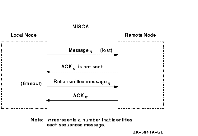
Retransmission typically occurs when a node runs out of a critical resource, such as large request packets (LRPs) or nonpaged pool, and a message is lost after it reaches the remote node. Other potential causes of retransmissions include overloaded LAN bridges, slow LAN adapters (such as the DELQA), and heavily loaded systems, which delay packet transmission or reception. Figure F-3 shows an unsuccessful transmission followed by a successful retransmission.
Figure F-3 Lost Messages Cause Retransmissions

Because the first message was lost, the local node does not receive acknowledgment (ACK) from the remote node. The remote node acknowledged the second (successful) transmission of the message.
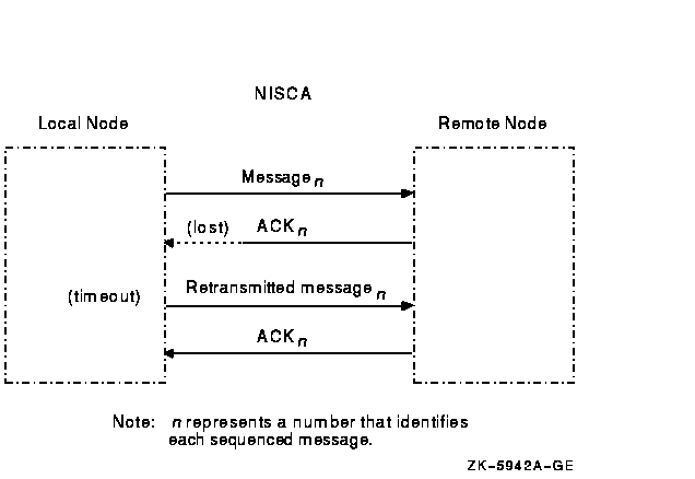
Retransmission can also occur if the cables are seated improperly, if the network is too busy and the datagram cannot be sent, or if the datagram is corrupted or lost during transmission either by the originating LAN adapter or by any bridges or repeaters. Figure F-4 illustrates another type of retransmission.
Figure F-4 Lost ACKs Cause Retransmissions

In Figure F-4, the remote node receives the message and transmits an acknowledgment (ACK) to the sending node. However, because the ACK from the receiving node is lost, the sending node retransmits the message.
F.6.2 Techniques for Troubleshooting
You can troubleshoot cluster retransmissions using a LAN protocol
analyzer for each LAN segment. If multiple segments are used for
cluster communications, then the LAN analyzers need to support a
distributed enable and trigger mechanism (see Section F.8). See also
Section G.1 for more information about how PEDRIVER chooses channels
on which to transmit datagrams.
Reference: Techniques for isolating the retransmitted
datagram using a LAN analyzer are discussed in Section F.10.2. See also
Appendix G for more information about congestion control and
PEDRIVER message retransmission.
F.7 Understanding NISCA Datagrams
Troubleshooting NISCA protocol communication problems requires an
understanding of the NISCA protocol packet that is exchanged across the
OpenVMS Cluster system.
F.7.1 Packet Format
The format of packets on the NISCA protocol is defined by the $NISCADEF macro, which is located in [DRIVER.LIS] on VAX systems and in [LIB.LIS] for Alpha systems on your CD listing disk.
Figure F-5 shows the general form of NISCA datagrams. A NISCA datagram consists of the following headers, which are usually followed by user data:
Figure F-5 NISCA Headers

Caution: The NISCA protocol is subject to change
without notice.
F.7.2 LAN Headers
The NISCA protocol is supported on LANs consisting of Ethernet and FDDI, described in Sections F.7.3 and F.7.4. These headers contain information that is useful for diagnosing problems that occur between LAN adapters.
Reference: See Section F.9.4 for methods of isolating
information in LAN headers.
F.7.3 Ethernet Header
Each datagram that is transmitted or received on the Ethernet is prefixed with an Ethernet header. The Ethernet header, shown in Figure F-6 and described in Table F-7, is 16 bytes long.
Figure F-6 Ethernet Header

| Field | Description |
|---|---|
| Destination address | LAN address of the adapter that should receive the datagram |
| Source address | LAN address of the adapter sending the datagram |
| Protocol type | NISCA protocol (60--07) hexadecimal |
| Length | Number of data bytes in the datagram following the length field |
Each datagram that is transmitted or received on the FDDI is prefixed with an FDDI header. The NISCA protocol uses mapped Ethernet format datagrams on the FDDI. The FDDI header, shown in Figure F-7 and described in Table F-8, is 23 bytes long.
Figure F-7 FDDI Header

| Field | Description |
|---|---|
| Frame control | NISCA datagrams are logical link control (LLC) frames with a priority value (5 x). The low-order 3 bits of the frame-control byte contain the priority value. All NISCA frames are transmitted with a nonzero priority field. Frames received with a zero-priority field are assumed to have traveled over an Ethernet segment because Ethernet packets do not have a priority value and because Ethernet-to-FDDI bridges generate a priority value of 0. |
| Destination address | LAN address of the adapter that should receive the datagram. |
| Source address | LAN address of the adapter sending the datagram. |
| SNAP SAP | Subnetwork access protocol; service access point. The value of the access point is AA--AA--03 hexadecimal. |
| SNAP PID | Subnetwork access protocol; protocol identifier. The value of the identifier is 00--00--00 hexadecimal. |
| Protocol type | NISCA protocol (60--07) hexadecimal. |
| Length | Number of data bytes in the datagram following the length field. |
The datagram exchange (DX) header for the OpenVMS Cluster protocol is used to address the data to the correct OpenVMS Cluster node. The DX header, shown in Figure F-8 and described in Table F-9, is 14 bytes long. It contains information that describes the OpenVMS Cluster connection between two nodes. See Section F.9.3 about methods of isolating data for the DX header.
Figure F-8 DX Header

| Field | Description |
|---|---|
| Destination SCS address | Manufactured using the address AA--00--04--00-- remote-node-SCSSYSTEMID. Append the remote node's SCSSYSTEMID system parameter value for the low-order 16 bits. This address represents the destination SCS transport address or the OpenVMS Cluster multicast address. |
| Cluster group number | The cluster group number specified by the system manager. See Chapter 8 for more information about cluster group numbers. |
| Source SCS address | Represents the source SCS transport address and is manufactured using the address AA--00--04--00-- local-node-SCSSYSTEMID. Append the local node's SCSSYSTEMID system parameter value as the low-order 16 bits. |
The channel control (CC) message is used to form and maintain working network paths between nodes in the OpenVMS Cluster system. The important fields for network troubleshooting are the datagram flags/type and the cluster password. Note that because the CC and TR headers occupy the same space, there is a TR/CC flag that identifies the type of message being transmitted over the channel. Figure F-9 shows the portions of the CC header needed for network troubleshooting, and Table F-10 describes these fields.
Figure F-9 CC Header

| Field | Description |
|---|---|
| Datagram type (bits <3:0>) | Identifies the type of message on the Channel Control level. The following table shows the datagrams and their functions. |
| Datagram flags (bits <7:4>) | Provide additional information about the control datagram. The following bits are defined: |
| Cluster password | Contains the cluster password. |
| Previous | Next | Contents | Index |
![[Go to the documentation home page]](../images/buttons/hp_bn_site_home.gif)
![[How to order documentation]](../images/buttons/hp_bn_order_docs.gif)
![[Help on this site]](../images/buttons/hp_bn_site_help.gif)
![[How to contact us]](../images/buttons/hp_bn_comments.gif)
|
| privacy and legal statement | ||
| 4477PRO_032.HTML | ||